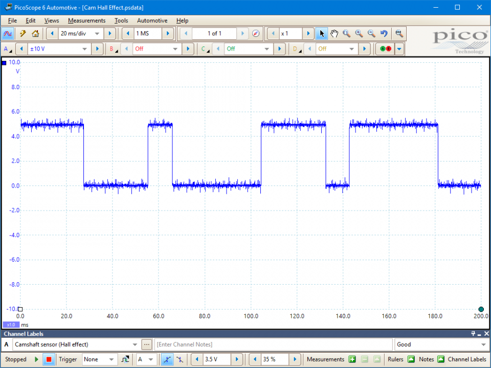
Voltage levels can also change from system to system depending on current flow and resistor values but a clear square wave pattern should be visible.
Hall effect sensor output voltage range.
Analog output sensors are available in voltage ranges of 4 5 to 10 5 4 5 to 12 or 6 6 to 12 6 vdc.
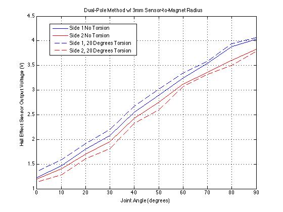
When a magnet approaches the face of the sensor the output voltage will increase or decrease depending on which side of the magnet you are using.
Internal protection functions are provided for reverse supply conditions load dump and output short circuit or overcurrent.
If the regulator is a 5 volt source the signal voltage is now 5 volts.
No external regulator required.
The sensors are accompanied by a pulse wheel.
Commonly seen in industrial applications such as the pictured pneumatic cylinder they are also used in consume.
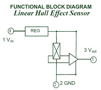
Linear output hall sensor.
The third hall effect sensor distance a 324 reads the magnetic field gradually.
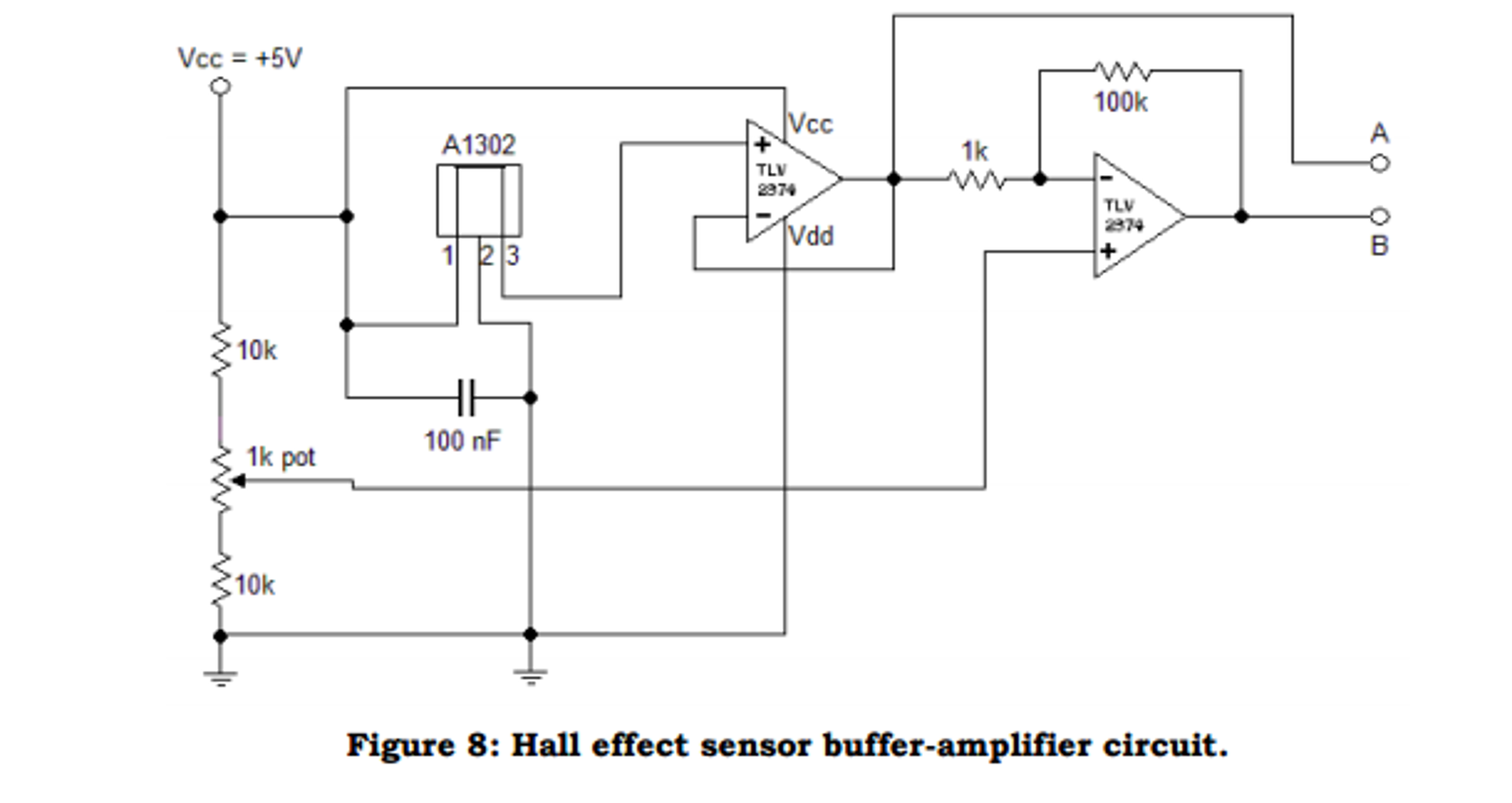
Its output voltage is directly proportional to the magnetic field strength through it.
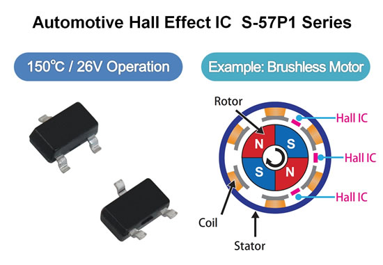
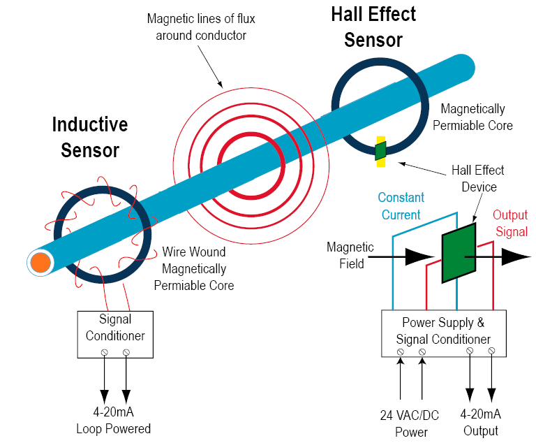
Hall effect sensors are used for proximity sensing positioning speed detection and current sensing applications.
Zero current output voltage is midway between the supply voltages that maintain a 4 to 8 volt differential.
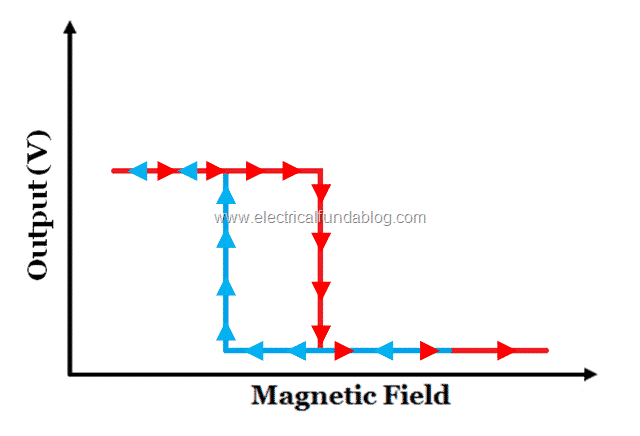
In response the digital sensor output switches either from low to high 0 v to 5 v or high to low 5 v to 0 v depending on the sensor circuitry.
A wide operating voltage range from 2 5 v to 38 v with reverse polarity protection up to 22 v makes the device suitable for a wide range of industrial applications.
Sensitivity 10 over temperature.
Superior temperature stability.
Hall effect magnetic sensor.
2 5 to 38 v.
A hall effect sensor is a device to measure the magnitude of a magnetic field.
When no magnetic field is sensed this sensor will output half of the source voltage 2 5v.
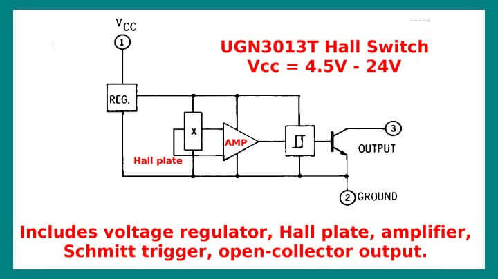
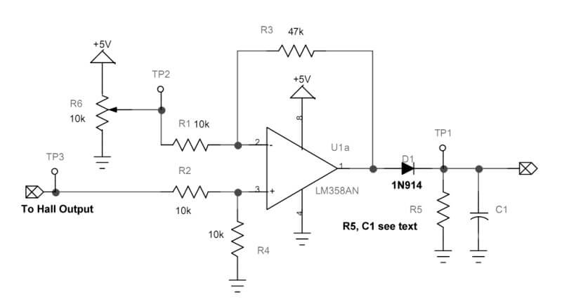
This output voltage can be quite small only a few microvolts even when subjected to strong magnetic fields so most commercially available hall effect devices are manufactured with built in dc amplifiers logic switching circuits and voltage regulators to improve the.
As the tooth passes beneath the hall sensor the circuit becomes activated and pulls this 5 volt signal to ground.
Frequently a hall sensor is combined with threshold detection so that it acts as and is called a switch.
Non zero current response is proportional to the voltage supplied and is linear to 60 amperes for this particular 25 a device.
They typically require a regulated supply voltage to operate accurately.
As they consume power hall effect cmp sensors require voltage feed and earth circuits.
Wide operating temperature range.
The output voltage called the hall voltage v h of the basic hall element is directly proportional to the strength of the magnetic field passing through the semiconductor material output h.
This cycle repeats itself to create the digital output from the gear tooth hall effect sensing device.
The voltage levels are different and much lower than a 3 wire hall effect abs sensor because of the low currents.
As the pulse wheel rotates it passes through and disturbs the sensor s magnetic field to modulate the hall voltage.
Source voltage is now present in the signal circuit.
Open in new find other hall effect latches switches.







.jpg)
